EIGRP – Various Packet Types

 EIGRP, Networking  Comments Off on EIGRP – Various Packet Types
Dec 132022
 

In this third post in our EIGRP series, let’s consider the various packet types used and their purpose.

Altogether, we encounter five packet types in EIGRP that are used to establish adjacencies and share routing information.

The packet types include: Hello, Acknowledgment, Update, Query and Reply.

Some of the EIGRP packet types are reliable and require an acknowledgment while others are unreliable and do not need an acknowledgment.

The OPCode field in the EIGRP packet header identifies the packet type:

OPCode 1: Update packet
OPCode 3: Query packet
OPCode 4: Reply packet
OPCode 5: Hello and ACK packets

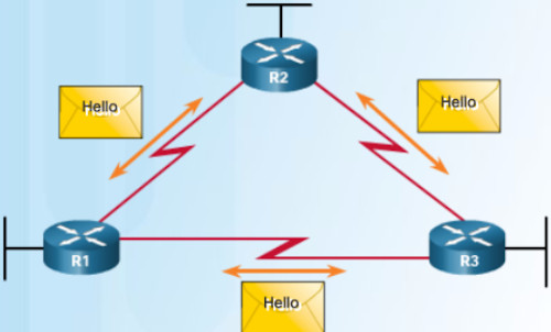
EIGRP Hello Packet

EIGRP Packet Types:

It’s time to consider each of the EIGRP packet types and their purpose.

* Hello:
# Discover and form adacencies with Neighbors (Other EIGRP routers in the NW)
# Hello packets are sent unreliably and do NOT require acknowledgements
# Continued receipt of Hellos maintains Neighbor Table
# Hello packets are sent via multicast

* Acknowledgment:
# Acknowledgements packets are “dataless” Hello packets with just a sequence number
# They indicate receipt of any EIGRP packet during a “reliable” (Reliable Transport Protocol) exchange
# Will acknowledge receipt of Update, Query and Reply packets

* Update:
# Transmit Routability and Reachability information with other EIGRP Neighbors
# Carry prefix and metric information
# Sent to initially exchange topology information or topology change
# Later Updates sent ONLY when necessary, such as when a new destination prefix becomes reachable or the cost of an already reachable destination prefix changes
# So updates are non-periodic, i.e., not sent at scheduled intervals
# EIGRP updates contain only needed routing information and are unicast to routers that require it
# Update packets can also be multicast (like when a link cost changes)
# Sent reliably and require acknowledgments

* Query:
# Query packets are sent when destinations go into Active state
# Used to get specific information from one or more Neighbors; Sent to search for another path during convergence
# Query packets are multicast to all peers on all interfaces except for the interface to the previous Successor
# Sent reliably and require acknowledgements

* Reply:
# Reply packets are unicast to the originator of the query
# Sent reliably and require acknowledgements

Reliable Packets:

Reliable packets require explicit acknowledgement from destination.

They are sequenced and retransmitted up to 16 times if not acknowledged.
Reliable packets are:
• Updates
• Queries
• Replies
• SIA-Queries
• SIA-Replies

Unreliable packets do not require acknowledgement from destination:
# Hello and ACK

How to Verify EIGRP Packets

A few days back, we did a basic EIGRP configuration.

As part of that basic EIGRP lab, we ran a bunch of commands including one that let us view the various EIGRP packets on a Router.

EIGRP Configuration on Packet Tracer

Take a look below at various EIGRP Packets on the three Routers R1, R2 and R3:

R1#sh ip eigrp traffic
IP-EIGRP Traffic Statistics for process 1
Hellos sent/received: 1211/1170
Updates sent/received: 8/6
Queries sent/received: 0/0
Replies sent/received: 0/0
Acks sent/received: 5/8
Input queue high water mark 1, 0 drops
SIA-Queries sent/received: 0/0
SIA-Replies sent/received: 0/0
R2#sh ip eigrp traffic
IP-EIGRP Traffic Statistics for process 1
Hellos sent/received: 1167/1162
Updates sent/received: 6/10
Queries sent/received: 0/0
Replies sent/received: 0/0
Acks sent/received: 10/6
Input queue high water mark 1, 0 drops
SIA-Queries sent/received: 0/0
SIA-Replies sent/received: 0/0
R3#sh ip eigrp traffic
IP-EIGRP Traffic Statistics for process 1
Hellos sent/received: 1140/1137
Updates sent/received: 7/5
Queries sent/received: 0/0
Replies sent/received: 0/0
Acks sent/received: 5/6
Input queue high water mark 1, 0 drops
SIA-Queries sent/received: 0/0
SIA-Replies sent/received: 0/0

How to Configure EIGRP Named Mode Authentication

 EIGRP, Networking, Security  Comments Off on How to Configure EIGRP Named Mode Authentication
Sep 282022
 

Configure EIGRP Named Mode Authentication

In this lab, we’ll configure authentication when running EIGRP in named mode.

While classic mode EIGRP offers only MD5 authentication, named mode EIGRP offers both MD5 and HMAC-SHA-256 authentication.

HMAC-SHA-256 authentication is, of course, the more secure version.

By the way, we can configure authentication between two routers with one running in EIGRP classic mode and the other in EIGRP named mode.

But both would have to use the MD5 authentication mode because EIGRP classic mode does not support HMAC-SHA-256.

Why EIGRP Authentication?

Authentication is essentially a security mechanism to prevent undesirable consequences in the network.

EIGRP router authentication ensures that unauthorized or rogue routers do not become neighbors with other corporate routers.

Unauthorized routers can result in invalid routes and in the worst case scenario lead to data loss or denial of service.

What Our Configuration Looks Like

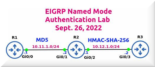
In our setup, we have three routers: R1, R2 and R3.

All of the routers are running EIGRP in named mode.

Between routers R1 and R2, we’ll be configuring MD5 authentication using a key chain.

Key chain does not need to be same on both routers but the Key ID and Key String must be same for both R1 and R2 routers.

Subsequently, we’ll go in for HMAC-SHA-256 authentication between R2 and R3.

HMAC-SHA-256 authentication can be done both without and with a key chain.

Most HMAC-SHA-256 authentication configurations that I have come across do not include a key chain.

Apparently, the key chain feature is not necessary if you’re going with HMAC-SHA-256 authentication.

Between R2 and R3, we’ll first do HMAC-SHA-256 authentication without a key chain and follow it up by adding a key chain to the configuration.

Following the two modes of authentication, we’ll run a bunch of Verify commands to ensure our goals are met.

Configure EIGRP Named Mode Authentication

We’ve configured the IP addresses on the three routers.

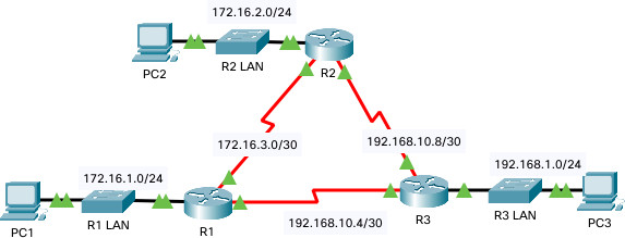
IP addresses have already been configured and you can check them by looking at the topology (see at top of this post).

Once again, all three routers are running EIGRP in named mode.
====================
Configure MD5 Authentication between R1 and R2
R1 Configuration
conf t
key chain ROMEO
key 1
key-string Cisco@123
exit
!
router eigrp TESTING
address-family ipv4 unicast autonomous-system 123
network 10.11.1.1 0.0.0.0
!
af-interface gig0/0
authentication mode md5
authentication key-chain ROMEO
!
exit-af-interface
exit-address-family

R2 Configuration
conf t
key chain ROMEO
key 1
key-string Cisco@123
exit
!
router eigrp NESTING
address-family ipv4 autonomous-system 123
network 10.11.1.2 0.0.0.0
network 10.12.1.1 0.0.0.0
!
af-interface gig0/1
authentication mode md5
authentication key-chain ROMEO
exit
! Configuring HMAC-SHA-256 Authentication between R2 and R3
af-interface gig0/2
authentication mode hmac-sha-256 7 Password@1
exit-af-interface
exit-address-family
exit
!
R3 Configuration
conf t
router eigrp PESTING
address-family ipv4 autonomous-system 123
network 10.12.1.2 0.0.0.0
! HMAC-SHA-256 Authentication between R3 and R2
af-interface gig0/3
authentication mode hmac-sha-256 7 Password@1
exit-af-interface
exit-address-family
exit

As you can see above, we’ve not configured a key chain for HMAC-SHA-256 authentication between R2 and R3.

Verify EIGRP Authentication

Having completed the configurations, let’s run a bunch of verify commands.

Verify MD5 Authentication between R1 and R2
R1#sh ip eigrp int detail gig0/0
EIGRP-IPv4 VR(TESTING) Address-Family Interfaces for AS(123)
Xmit Queue PeerQ Mean Pacing Time Multicast Pending
Interface Peers Un/Reliable Un/Reliable SRTT Un/Reliable Flow Timer Routes
Gi0/0 1 0/0 0/0 1594 0/0 7972 0
Hello-interval is 5, Hold-time is 15
Split-horizon is enabled
Next xmit serial
Packetized sent/expedited: 2/0
Hello’s sent/expedited: 92/2
Un/reliable mcasts: 0/2 Un/reliable ucasts: 2/2
Mcast exceptions: 0 CR packets: 0 ACKs suppressed: 0
Retransmissions sent: 1 Out-of-sequence rcvd: 0
Topology-ids on interface – 0
Authentication mode is md5, key-chain is “ROMEO”
Topologies advertised on this interface: base
Topologies not advertised on this interface:

Verify HMAC-SHA-256 Authentication between R2 and R3
R2#sh ip eigrp int detail gig0/2
EIGRP-IPv4 VR(NESTING) Address-Family Interfaces for AS(123)
Xmit Queue PeerQ Mean Pacing Time Multicast Pending
Interface Peers Un/Reliable Un/Reliable SRTT Un/Reliable Flow Timer Routes
Gi0/2 1 0/0 0/0 0 0/0 50 0
Hello-interval is 5, Hold-time is 15
Split-horizon is enabled
Next xmit serial
Packetized sent/expedited: 1/0
Hello’s sent/expedited: 103/2
Un/reliable mcasts: 0/1 Un/reliable ucasts: 3/3
Mcast exceptions: 0 CR packets: 0 ACKs suppressed: 0
Retransmissions sent: 2 Out-of-sequence rcvd: 0
Topology-ids on interface – 0
Authentication mode is HMAC-SHA-256, key-chain is not set
Topologies advertised on this interface: base
Topologies not advertised on this interface:

Check Key Chain on R1
R1#show key chain
Key-chain ROMEO:
key 1 — text “Cisco@123”
accept lifetime (always valid) – (always valid) [valid now]
send lifetime (always valid) – (always valid) [valid now]

Check Key Chain on R2
R2#show key chain
Key-chain ROMEO:
key 1 — text “Cisco@123”
accept lifetime (always valid) – (always valid) [valid now]
send lifetime (always valid) – (always valid) [valid now]

Adding Key Chain on R2 and R3 (HMAC-SHA-256 mode)

R2 Configuration
conf t
key chain JULIET-CHAIN
key 2
key-string Bisco@123
exit
!
router eigrp NESTING
address-family ipv4 autonomous-system 123
af-interface gig0/2
authentication key-chain JULIET-CHAIN
exit

R3 Configuration
conf t
key chain JULIET-CHAIN
key 2
key-string Bisco@123
exit
!
router eigrp PESTING
address-family ipv4 autonomous-system 123
af-interface gig0/3
authentication key-chain JULIET-CHAIN
exit
=================
Verify R2 with HMAC-SHA-256 AND Key Chain
R2#show ip eigrp int detail gig0/2
EIGRP-IPv4 VR(NESTING) Address-Family Interfaces for AS(123)
Xmit Queue PeerQ Mean Pacing Time Multicast Pending
Interface Peers Un/Reliable Un/Reliable SRTT Un/Reliable Flow Timer Routes
Gi0/2 1 0/0 0/0 10 0/0 50 0
Hello-interval is 5, Hold-time is 15
Split-horizon is enabled
Next xmit serial
Packetized sent/expedited: 2/0
Hello’s sent/expedited: 1518/3
Un/reliable mcasts: 0/2 Un/reliable ucasts: 5/4Mcast exceptions: 0 CR packets: 0 ACKs suppressed: 0
Retransmissions sent: 2 Out-of-sequence rcvd: 1
Topology-ids on interface – 0
Authentication mode is HMAC-SHA-256, key-chain is “JULIET-CHAIN”
Topologies advertised on this interface: base
Topologies not advertised on this interface:

Verify Authentication on R3 AFTER Adding Key Chain
R3#show key chain
Key-chain JULIET-CHAIN:
key 2 — text “Bisco@123”
accept lifetime (always valid) – (always valid) [valid now]
send lifetime (always valid) – (always valid) [valid now]

How to Configure DMVPN

 Networking, Security  Comments Off on How to Configure DMVPN
Sep 232022
 

DMVPN Configuration

Dynamic Multipoint Virtual Private Network (DMVPN) owes its popularity to two primary reasons: scalability and simplicity of configuration.

In large organizations with lots of branches, configuring dozens of point-to-point VPN tunnels is an error-prone and cumbersome exercise.

So Cisco introduced the DMVPN technology nearly two decades ago.

DMVPN finds favor for another reason: It supports all routing protocols except IS-IS.

DMVPN Foundation Technologies

* Next Hop Resolution Protocol (NHRP): A layer 2 resolution protocol and cache used in DMVPN to map a tunnel IP address to an Non-Broadcast Multicast (NBMA) public IP address.
* Multipoint GRE (mGRE) interface: A single GRE interface that supports multiple GRE/IPsec tunnels and endpoints; also unlike with regular GRE, we do not define a tunnel destination with mGRE tunnels.
* IPsec: For protecting the DMVPN tunnels; both IKEv1 and IKEv2 are supported; DMVPN can be deployed without IPsec encryption but why would you want to.

Over the years, DMVPN has evolved through three phases but the current focus is only on Phase 3.

DMVPN – Phase 3 Configuration

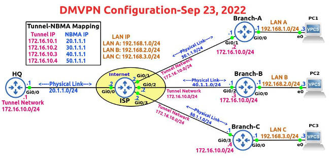
In our topology (see at the top of this post), the IP addresses of the routers and PCs have already been configured.

You can check the IP address, Network ID, Subnet Mask and Interface IDs in the topology diagram.

So we’ll get straight down to DMVPN and IPsec configuration.

Toward the end of this post, we’ll run a few show commands.

! DMVPN Configuration
HQ is our Hub router and Branch A, Branch B and Branch C are the Spoke routers.

! HQ Router
! Configure Default Static Route on HQ Router
conf t
ip route 0.0.0.0 0.0.0.0 20.1.1.2
exit

!mGRE Configuration on HQ (Hub) Router
Configure Tunnel
conf t
interface tunnel 0
ip address 172.16.10.1 255.255.255.0
ip mtu 1400
ip tcp adjust-mss 1360
tunnel source gig0/0
tunnel mode gre multipoint

tunnel key 123
no shut
exit

! Configuring NHRP on Tunnel Interfaces of HQ Router
interface tunnel 0
ip nhrp network-id 1
ip nhrp authentication Cisco567

ip nhrp map multicast dynamic
ip nhrp redirect
exit

!Configure Dynamic Routing
router eigrp 5
network 172.16.10.0 0.0.0.255
no auto-summary
end

! Configure EIGRP Hop Issues on HQ (Hub) Router
conf t
interface tunnel 0
no ip next-hop-self eigrp 5
no ip split-horizon eigrp 5
exit
============================
Let’s configure the Spoke Routers (aka Branch Routers) now.

! Branch-A Router Configuration
Configure Default Static Route to ISP Router
conf t
ip route 0.0.0.0 0.0.0.0 30.1.1.2
end

!mGRE Configuration on Branch-A
Configure Tunnel on Branch A
conf t
interface tunnel 0
ip address 172.16.10.2 255.255.255.0
ip mtu 1400
ip tcp adjust-mss 1360
tunnel source g0/1
tunnel mode gre multipoint

tunnel key 123
no shut

! Configuring NHRP Inside the Tunnel Interfaces
conf t
interface tunnel 0

ip nhrp network-id 1
ip nhrp authentication Cisco567
ip nhrp map 172.16.10.1 20.1.1.1
ip nhrp map multicast 20.1.1.1
ip nhrp nhs 172.16.10.1

ip nhrp shortcut
exit

! Configure Dynamic Routing (Tunnel & LAN)
conf t
router eigrp 5
network 172.16.10.0 0.0.0.255
network 192.168.1.0 0.0.0.255
no auto-summary
end
============================
! Branch-B Router Configuration
Configure Default Static Route to ISP Router
conf t
ip route 0.0.0.0 0.0.0.0 40.1.1.2
end

!mGRE Configuration on Branch-B
Configure Tunnel
conf t
interface tunnel 0
ip address 172.16.10.3 255.255.255.0
ip mtu 1400
ip tcp adjust-mss 1360
tunnel source gig0/2
tunnel mode gre multipoint

tunnel key 123
no shut
exit

! Configuring NHRP on Tunnel Interfaces
interface tunnel 0
ip nhrp network-id 1
ip nhrp authentication Cisco567

ip nhrp map 172.16.10.1 20.1.1.1
ip nhrp map multicast 20.1.1.1
ip nhrp nhs 172.16.10.1

ip nhrp shortcut
exit

! Configure Dynamic Routing (Tunnel & LAN)
router eigrp 5
network 192.168.2.0 0.0.0.255
network 172.16.10.0 0.0.0.255
no auto-summary
end
============================
! Branch-C Router Configuration
Configure Default Static Route to ISP Router
conf t
ip route 0.0.0.0 0.0.0.0 50.1.1.2

!mGRE Configuration on Branch-C
Configure Tunnel
interface tunnel 0
ip address 172.16.10.4 255.255.255.0
ip mtu 1400
ip tcp adjust-mss 1360
tunnel source g0/3
tunnel mode gre multipoint
sh ip int br
tunnel key 123
no shut
exit

! Configuring NHRP on the Tunnel Interfaces
interface tunnel 0

ip nhrp network-id 1
ip nhrp authentication Cisco567

ip nhrp map 172.16.10.1 20.1.1.1
ip nhrp map multicast 20.1.1.1
ip nhrp nhs 172.16.10.1

ip nhrp shortcut
exit

! Configure Dynamic Routing (Tunnel & LAN)
router eigrp 5
network 192.168.3.0 0.0.0.255
network 172.16.10.0 0.0.0.255
no auto-summary
end
============================

IPsec Configuration

Let’s now work on the IPsec configuration on the Hub and Spokes.

Apply IPSec Configuration to Routers
HQ Router
conf t
crypto isakmp policy 25
hash sha256
authentication pre-share
group 16
encryption aes 256
exit

crypto isakmp key Cisco123! address 0.0.0.0 0.0.0.0
crypto ipsec transform-set JACK esp-aes 256 esp-sha256-hmac
exit

crypto ipsec profile JAN-2022
set transform-set JACK

interface tunnel 0
tunnel protection ipsec profile JAN-2022

Branch-A Router
conf t
crypto isakmp policy 25
hash sha256
authentication pre-share
encryption aes 256
group 16
exit

crypto isakmp key Cisco123! address 0.0.0.0 0.0.0.0
crypto ipsec transform-set JACK esp-aes 256 esp-sha256-hmac
exit

crypto ipsec profile JAN-2022
set transform-set JACK
exit

interface tunnel 0
tunnel protection ipsec profile JAN-2022
exit
===================================
Branch-B Router
conf t
crypto isakmp policy 25
hash sha256
authentication pre-share
encryption aes 256
group 16
exit

crypto isakmp key Cisco123! address 0.0.0.0 0.0.0.0
crypto ipsec transform-set JACK esp-aes 256 esp-sha256-hmac
exit

crypto ipsec profile JAN-2022
set transform-set JACK
exit

interface tunnel 0
tunnel protection ipsec profile JAN-2022
exit
===================================
Branch-C Router
conf t
crypto isakmp policy 25
hash sha256
authentication pre-share
encryption aes 256
group 16
exit

crypto isakmp key Cisco123! address 0.0.0.0 0.0.0.0
crypto ipsec transform-set JACK esp-aes 256 esp-sha256-hmac
exit

crypto ipsec profile JAN-2022
set transform-set JACK
exit

interface tunnel 0
tunnel protection ipsec profile JAN-2022
exit
===================================

Verify DMVPN/IPsec

Let’s run a bunch of show commands now.

Branch-A#show dmvpn
Legend: Attrb –> S – Static, D – Dynamic, I – Incomplete
N – NATed, L – Local, X – No Socket
T1 – Route Installed, T2 – Nexthop-override
C – CTS Capable
# Ent –> Number of NHRP entries with same NBMA peer
NHS Status: E –> Expecting Replies, R –> Responding, W –> Waiting
UpDn Time –> Up or Down Time for a Tunnel
==========================================================================
Interface: Tunnel0, IPv4 NHRP Details
Type:Spoke, NHRP Peers:1,

# Ent Peer NBMA Addr Peer Tunnel Add State UpDn Tm Attrb
—– ————— ————— —– ——– —–

1 20.1.1.1 172.16.10.1 UP 00:11:18 S

Two Trace Route Tests
In the first trace route test, we notice that PC1 goes via the Hub, i.e., HQ router but in the second Ping we see the direct Spoke-to-Spoke communication.

Trace Route Test 1
PC1> trace 192.168.3.3
trace to 192.168.3.3, 8 hops max, press Ctrl+C to stop
1 192.168.1.1 9.130 ms 4.943 ms 3.239 ms
2 172.16.10.1 28.634 ms 26.395 ms 24.367 ms
3 172.16.10.4 55.470 ms 56.578 ms 51.083 ms
4 *192.168.3.3 92.779 ms (ICMP type:3, code:3, Destination port unreachable)

Trace Route Test 2
PC1> trace 192.168.3.3
trace to 192.168.3.3, 8 hops max, press Ctrl+C to stop
1 192.168.1.1 5.135 ms 4.122 ms 4.057 ms
2 172.16.10.4 30.269 ms 22.106 ms 15.984 ms
3 *192.168.3.3 20.189 ms (ICMP type:3, code:3, Destination port unreachable)

Branch-A#show dmvpn
Legend: Attrb –> S – Static, D – Dynamic, I – Incomplete
N – NATed, L – Local, X – No Socket
T1 – Route Installed, T2 – Nexthop-override
C – CTS Capable
# Ent –> Number of NHRP entries with same NBMA peer
NHS Status: E –> Expecting Replies, R –> Responding, W –> Waiting
UpDn Time –> Up or Down Time for a Tunnel
==========================================================================
Interface: Tunnel0, IPv4 NHRP Details
Type:Spoke, NHRP Peers:2,

# Ent Peer NBMA Addr Peer Tunnel Add State UpDn Tm Attrb
—– ————— ————— —– ——– —–
1 20.1.1.1 172.16.10.1 UP 00:12:21 S
2 50.1.1.1 172.16.10.4 UP 00:00:22 DT1
172.16.10.4 UP 00:00:22 DT2

Branch-A#show ip nhrp shortcut
172.16.10.4/32 via 172.16.10.4
Tunnel0 created 00:03:59, expire 01:56:01
Type: dynamic, Flags: router nhop rib
NBMA address: 50.1.1.1
192.168.3.0/24 via 172.16.10.4
Tunnel0 created 00:03:58, expire 01:56:00
Type: dynamic, Flags: router rib nho
NBMA address: 50.1.1.1
Branch-A#

Branch-A#show dmvpn detail
Legend: Attrb –> S – Static, D – Dynamic, I – Incomplete
N – NATed, L – Local, X – No Socket
T1 – Route Installed, T2 – Nexthop-override
C – CTS Capable
# Ent –> Number of NHRP entries with same NBMA peer
NHS Status: E –> Expecting Replies, R –> Responding, W –> Waiting
UpDn Time –> Up or Down Time for a Tunnel
==========================================================================
Interface Tunnel0 is up/up, Addr. is 172.16.10.2, VRF “”
Tunnel Src./Dest. addr: 30.1.1.1/MGRE, Tunnel VRF “”
Protocol/Transport: “multi-GRE/IP”, Protect “JAN-2022”
Interface State Control: Disabled
nhrp event-publisher : Disabled

IPv4 NHS:
172.16.10.1 RE priority = 0 cluster = 0
Type:Spoke, Total NBMA Peers (v4/v6): 3

# Ent Peer NBMA Addr Peer Tunnel Add State UpDn Tm Attrb Target Network
—– ————— ————— —– ——– —– —————–
1 20.1.1.1 172.16.10.1 UP 00:20:03 S 172.16.10.1/32
2 50.1.1.1 172.16.10.4 UP 00:08:05 DT1 172.16.10.4/32
50.1.1.1 172.16.10.4 UP 00:08:05 DT2 192.168.3.0/24
1 30.1.1.1 172.16.10.2 UP 00:08:05 DLX 192.168.1.0/24
Crypto Session Details:
——————————————————————————–
Interface: Tunnel0
Session: [0x10D7B838]
Session ID: 0
IKEv1 SA: local 30.1.1.1/500 remote 20.1.1.1/500 Active
Capabilities:(none) connid:1001 lifetime:23:39:54
Crypto Session Status: UP-ACTIVE
fvrf: (none), Phase1_id: 20.1.1.1
IPSEC FLOW: permit 47 host 30.1.1.1 host 20.1.1.1
Active SAs: 4, origin: crypto map
Inbound: #pkts dec’ed 279 drop 0 life (KB/Sec) 4286401/2395
Outbound: #pkts enc’ed 280 drop 0 life (KB/Sec) 4286401/2395
Outbound SPI : 0x46732BB6, transform : esp-256-aes esp-sha256-hmac
Socket State: Open

Interface: Tunnel0
Session: [0x10D7B930]
Session ID: 0
IKEv1 SA: local 30.1.1.1/500 remote 50.1.1.1/500 Active
Capabilities:(none) connid:1002 lifetime:23:51:54
Session ID: 0
IKEv1 SA: local 30.1.1.1/500 remote 50.1.1.1/500 Active
Capabilities:(none) connid:1003 lifetime:23:51:54
Crypto Session Status: UP-ACTIVE
fvrf: (none), Phase1_id: 50.1.1.1
IPSEC FLOW: permit 47 host 30.1.1.1 host 50.1.1.1
Active SAs: 4, origin: crypto map
Inbound: #pkts dec’ed 9 drop 0 life (KB/Sec) 4260667/3114
Outbound: #pkts enc’ed 8 drop 0 life (KB/Sec) 4260667/3114
Outbound SPI : 0x2DE78CC7, transform : esp-256-aes esp-sha256-hmac
Socket State: Open

Pending DMVPN Sessions:
Branch-A#

Ping Tests

Let’s run a couple of pings to verify reachability.

PC1> ping 192.168.3.3
84 bytes from 192.168.3.3 icmp_seq=1 ttl=62 time=33.569 ms
84 bytes from 192.168.3.3 icmp_seq=2 ttl=62 time=20.158 ms
84 bytes from 192.168.3.3 icmp_seq=3 ttl=62 time=25.318 ms
84 bytes from 192.168.3.3 icmp_seq=4 ttl=62 time=21.351 ms
84 bytes from 192.168.3.3 icmp_seq=5 ttl=62 time=23.523 ms

PC1> ping 192.168.2.3

84 bytes from 192.168.2.3 icmp_seq=1 ttl=61 time=75.934 ms
84 bytes from 192.168.2.3 icmp_seq=2 ttl=62 time=23.839 ms
84 bytes from 192.168.2.3 icmp_seq=3 ttl=62 time=21.544 ms
84 bytes from 192.168.2.3 icmp_seq=4 ttl=62 time=21.184 ms
84 bytes from 192.168.2.3 icmp_seq=5 ttl=62 time=21.815 ms

Branch-A#sh ip route next-hop-override | section H|%
o – ODR, P – periodic downloaded static route, H – NHRP, l – LISP
+ – replicated route, % – next hop override, p – overrides from PfR
H 172.16.10.3/32 is directly connected, 00:00:47, Tunnel0
H 172.16.10.4/32 is directly connected, 00:27:45, Tunnel0
192.168.1.0/24 is variably subnetted, 2 subnets, 2 masks
D % 192.168.2.0/24 [90/28160256] via 172.16.10.3, 00:39:43, Tunnel0
[NHO][90/255] via 172.16.10.3, 00:00:47, Tunnel0
D % 192.168.3.0/24 [90/28160256] via 172.16.10.4, 00:39:43, Tunnel0
[NHO][90/255] via 172.16.10.4, 00:27:45, Tunnel0
Branch-A#

Verify Routing on Branch A & HQ Routers
Check Branch A Routing
Branch-A#show ip route
Codes: L – local, C – connected, S – static, R – RIP, M – mobile, B – BGP
D – EIGRP, EX – EIGRP external, O – OSPF, IA – OSPF inter area
N1 – OSPF NSSA external type 1, N2 – OSPF NSSA external type 2
E1 – OSPF external type 1, E2 – OSPF external type 2
i – IS-IS, su – IS-IS summary, L1 – IS-IS level-1, L2 – IS-IS level-2
ia – IS-IS inter area, * – candidate default, U – per-user static route
o – ODR, P – periodic downloaded static route, H – NHRP, l – LISP
a – application route
+ – replicated route, % – next hop override, p – overrides from PfR
Gateway of last resort is 30.1.1.2 to network 0.0.0.0
S* 0.0.0.0/0 [1/0] via 30.1.1.2
30.0.0.0/8 is variably subnetted, 2 subnets, 2 masks
C 30.1.1.0/24 is directly connected, GigabitEthernet0/1
L 30.1.1.1/32 is directly connected, GigabitEthernet0/1
172.16.0.0/16 is variably subnetted, 4 subnets, 2 masks
C 172.16.10.0/24 is directly connected, Tunnel0
L 172.16.10.2/32 is directly connected, Tunnel0
H 172.16.10.3/32 is directly connected, 00:00:02, Tunnel0
H 172.16.10.4/32 is directly connected, 00:00:31, Tunnel0
192.168.1.0/24 is variably subnetted, 2 subnets, 2 masks
C 192.168.1.0/24 is directly connected, GigabitEthernet0/0
L 192.168.1.1/32 is directly connected, GigabitEthernet0/0
D % 192.168.2.0/24 [90/28160256] via 172.16.10.3, 02:48:52, Tunnel0
D % 192.168.3.0/24 [90/28160256] via 172.16.10.4, 02:48:52, Tunnel0

Verify HQ Routing
HQ#sh ip route
Codes: L – local, C – connected, S – static, R – RIP, M – mobile, B – BGP
D – EIGRP, EX – EIGRP external, O – OSPF, IA – OSPF inter area
N1 – OSPF NSSA external type 1, N2 – OSPF NSSA external type 2
E1 – OSPF external type 1, E2 – OSPF external type 2
i – IS-IS, su – IS-IS summary, L1 – IS-IS level-1, L2 – IS-IS level-2
ia – IS-IS inter area, * – candidate default, U – per-user static route
o – ODR, P – periodic downloaded static route, H – NHRP, l – LISP
a – application route
+ – replicated route, % – next hop override, p – overrides from PfR

Gateway of last resort is 20.1.1.2 to network 0.0.0.0

S* 0.0.0.0/0 [1/0] via 20.1.1.2
20.0.0.0/8 is variably subnetted, 2 subnets, 2 masks
C 20.1.1.0/24 is directly connected, GigabitEthernet0/0
L 20.1.1.1/32 is directly connected, GigabitEthernet0/0
172.16.0.0/16 is variably subnetted, 2 subnets, 2 masks
C 172.16.10.0/24 is directly connected, Tunnel0
L 172.16.10.1/32 is directly connected, Tunnel0
D 192.168.1.0/24 [90/26880256] via 172.16.10.2, 02:52:53, Tunnel0
D 192.168.2.0/24 [90/26880256] via 172.16.10.3, 02:52:53, Tunnel0
D 192.168.3.0/24 [90/26880256] via 172.16.10.4, 02:52:53, Tunnel0

Examine IP NHRP on Branch A & HQ Routers
Branch-A#sh ip nhrp brief
****************************************************************************
NOTE: Link-Local, No-socket and Incomplete entries are not displayed
****************************************************************************
Legend: Type –> S – Static, D – Dynamic
Flags –> u – unique, r – registered, e – temporary, c – claimed
a – authoritative, t – route
============================================================================

Intf NextHop Address NBMA Address
Target Network T/Flag
——– ——————————————- —— —————-
Tu0 172.16.10.1 20.1.1.1
172.16.10.1/32 S/
Tu0 172.16.10.3 40.1.1.1
172.16.10.3/32 D/t
192.168.2.0/24 D/t
Tu0 172.16.10.4 50.1.1.1
172.16.10.4/32 D/t
192.168.3.0/24 D/t
Branch-A#

HQ#sh ip nhrp brief
****************************************************************************
NOTE: Link-Local, No-socket and Incomplete entries are not displayed
****************************************************************************
Legend: Type –> S – Static, D – Dynamic
Flags –> u – unique, r – registered, e – temporary, c – claimed
a – authoritative, t – route
============================================================================
Intf NextHop Address NBMA Address
Target Network T/Flag
——– ——————————————- —— —————-
Tu0 172.16.10.2 30.1.1.1
172.16.10.2/32 D/ur
Tu0 172.16.10.3 40.1.1.1
172.16.10.3/32 D/ur
Tu0 172.16.10.4 50.1.1.1
172.16.10.4/32 D/ur
HQ#

Verify Tunnel Interfaces on Branch A and HQ Routers
Branch-A#sh int tun0
Tunnel0 is up, line protocol is up
Hardware is Tunnel
Internet address is 172.16.10.2/24
MTU 17912 bytes, BW 100 Kbit/sec, DLY 50000 usec,
reliability 255/255, txload 1/255, rxload 1/255
Encapsulation TUNNEL, loopback not set
Keepalive not set
Tunnel linestate evaluation up
Tunnel source 30.1.1.1 (GigabitEthernet0/1)
Tunnel Subblocks:
src-track:
Tunnel0 source tracking subblock associated with GigabitEthernet0/1
Set of tunnels with source GigabitEthernet0/1, 1 member (includes iterators), on interface
Tunnel protocol/transport multi-GRE/IP
Key 0x7B, sequencing disabled
Checksumming of packets disabled
Tunnel TTL 255, Fast tunneling enabled
Tunnel transport MTU 1472 bytes
Tunnel transmit bandwidth 8000 (kbps)
Tunnel receive bandwidth 8000 (kbps)
Tunnel protection via IPSec (profile “JAN-2022”)
Last input 00:00:01, output never, output hang never
Last clearing of “show interface” counters 00:21:53
Input queue: 0/75/0/0 (size/max/drops/flushes); Total output drops: 6
Queueing strategy: fifo
Output queue: 0/0 (size/max)
5 minute input rate 0 bits/sec, 0 packets/sec
5 minute output rate 0 bits/sec, 0 packets/sec
308 packets input, 27694 bytes, 0 no buffer
Received 0 broadcasts (0 IP multicasts)
0 runts, 0 giants, 0 throttles
0 input errors, 0 CRC, 0 frame, 0 overrun, 0 ignored, 0 abort
314 packets output, 29020 bytes, 0 underruns
0 output errors, 0 collisions, 0 interface resets
0 unknown protocol drops
0 output buffer failures, 0 output buffers swapped out
Branch-A#

HQ#sh int tun0
Tunnel0 is up, line protocol is up
Hardware is Tunnel
Internet address is 172.16.10.1/24
MTU 17912 bytes, BW 100 Kbit/sec, DLY 50000 usec,
reliability 255/255, txload 1/255, rxload 1/255
Encapsulation TUNNEL, loopback not set
Keepalive not set
Tunnel linestate evaluation up
Tunnel source 20.1.1.1 (GigabitEthernet0/0)
Tunnel Subblocks:
src-track:
Tunnel0 source tracking subblock associated with GigabitEthernet0/0
Set of tunnels with source GigabitEthernet0/0, 1 member (includes iterators), on interface
Tunnel protocol/transport multi-GRE/IP
Key 0x7B, sequencing disabled
Checksumming of packets disabled
Tunnel TTL 255, Fast tunneling enabled
Tunnel transport MTU 1472 bytes
Tunnel transmit bandwidth 8000 (kbps)
Tunnel receive bandwidth 8000 (kbps)
Tunnel protection via IPSec (profile “JAN-2022”)
Last input 00:00:01, output never, output hang never
Last clearing of “show interface” counters 00:36:16
Input queue: 0/75/0/0 (size/max/drops/flushes); Total output drops: 2
Queueing strategy: fifo
Output queue: 0/0 (size/max)
5 minute input rate 0 bits/sec, 0 packets/sec
5 minute output rate 0 bits/sec, 0 packets/sec
1441 packets input, 127644 bytes, 0 no buffer
Received 0 broadcasts (0 IP multicasts)
0 runts, 0 giants, 0 throttles
0 input errors, 0 CRC, 0 frame, 0 overrun, 0 ignored, 0 abort
1446 packets output, 129382 bytes, 0 underruns
0 output errors, 0 collisions, 0 interface resets
0 unknown protocol drops
0 output buffer failures, 0 output buffers swapped out

 Posted by at 5:17 pm  Tagged with:

IPSEC VTI Site-to-Site VPN

 Networking, Security  Comments Off on IPSEC VTI Site-to-Site VPN
Sep 192022
 

IPSEC Virtual Tunnel Interface Site to Site VPN

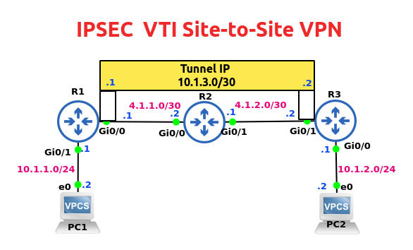
Let’s configure a VTI site-to-site Virtual Private Network in this lab.

In this VPN lab, we’re running IPSEC as the native protocol on the tunnel interface.

We’re not using Generic Routing Encapsulation (GRE) in this VPN lab.

The lab will also demonstrate use of a dynamic routing protocol (EIGRP) between routers R1 and R3 on the Tunnel interface and for the two LAN segments.

So obviously we’ll also be using Multicast over the tunnel interface.

After the IPSEC VPN is configured, we’ll run a bunch of show/verify commands.

Why VTI?

So why would we want to use static VTI/IPsec to create a site-to-site VPN instead of the GRE/IPsec option or the older cryptomap/ACL based VPN?

For one, the GRE header adds an extra 4-bytes. So avoiding GRE eliminates that bandwidth overhead.

Also, unlike with the cryptomap/ACL based VPN option in the static VPN model the IPsec tunnel is “on” all the time.

VTI’s support for QoS and multicast (just like with GRE/IPsec) means we can use dynamic routing protocols here.

Then there’s the issue of scalability. Some networking experts consider VTI more scalable than GRE/IPsec but if you ask me the scalability issue in larger networks is better addressed with Dynamic Multipoint Virtual Private Networks (DMVPN).

This lab is running on the GNS3 network simulation tool.

Configurations

IP addresses of the end-devices on the LAN segment and of the three routers have already been configured.

You can check them by viewing the topology diagram at the top of this post.

We’ll start with static routing to ensure end-end connectivity from R1 to R3.

Configure Static Routing on R1 & R2

R1
conf t
ip route 0.0.0.0 0.0.0.0 4.1.1.2
end

R3
conf t
ip route 0.0.0.0 0.0.0.0 4.1.2.1
end

VTI IPsec Configuration

Now it’s time for the meat of this lab, the VTI IPSec configuration to build the Virtual Private Network (VPN).

R1 VTI Configuration
IKE Phase 1
*********************
Set Global IKE policy
Configure Phase 1 Tunnel (ISAKMP Parameters)

conf t
crypto isakmp policy 10
encryption aes 256
hash sha256
authentication pre-share
group 16
lifetime 3600

crypto isakmp key Cisco123 address 4.1.2.2

Configure Phase 2 Tunnel on R1
crypto ipsec transform-set BTS esp-aes 256 esp-sha256-hmac
mode tunnel

crypto ipsec profile JULY-2022-PROFILE
set transform-set BTS
exit

! Configure Tunnel Interface
int tun 0
ip address 10.1.3.1 255.255.255.252
tunnel source g0/0
tunnel destination 4.1.2.2
tunnel mode ipsec ipv4
tunnel protection ipsec profile JULY-2022-PROFILE
qos pre-classify
end

Note: The tunnel mode ipsec ipv4 command is not used in GRE/IPsec VPN.

Having completed the IPSec configuration for R1, we’re ready  to configure R3.

Except for the lifetime configuration, the other parameters in the Phase 1 Tunnel should match on R1 and R3 routers.

R3 VTI Configuration
*********************
Configure Phase 1 Tunnel
conf t
crypto isakmp policy 10
encryption aes 256
hash sha256
authentication pre-share
group 16
lifetime 3600

crypto isakmp key Cisco123 address 4.1.1.1

Configure Phase 2 Tunnel on R3
crypto ipsec transform-set BTS esp-aes 256 esp-sha256-hmac
mode tunnel

crypto ipsec profile JULY-2022-PROFILE
set transform-set BTS
exit
Configure Tunnel Interface
int tun 0
ip address 10.1.3.2 255.255.255.252
tunnel source g0/1
tunnel destination 4.1.1.1
tunnel mode ipsec ipv4

tunnel protection ipsec profile JULY-2022-PROFILE
qos pre-classify
end
===================================================================

EIGRP Protocol for Tunnel & LAN

Let’s set up a dynamic routing protocol for the LAN segments and for the tunnel.

We’ll use EIGRP this time.

R1
conf t
router eigrp 12
network 10.1.1.0 0.0.0.255
network 10.1.3.0 0.0.0.3
no auto-summary
end

R3
conf t
router eigrp 12
network 10.1.2.0 0.0.0.255
network 10.1.3.0 0.0.0.3
no auto-summary
end
===================================================================

Key IPSec Show Commands

There are a whole bunch of show or verify commands when it comes to a Site-to-Site VPN configuration.

sh run | s crypto
sh crypto isakmp policy
sh crypto isakmp key
sh crypto isakmp sa
sh int tun0
sh crypto ipsec profile
sh crypto ipsec transform-set

We’ll run them all below.

It’s always a good idea to check our IPSec configuration with show run | section crypto before we dive into other show commands.

This also gives us an opportunity to identify errors if any.

R1#sh run | section crypto
crypto isakmp policy 10
encr aes 256
hash sha256
authentication pre-share
group 16
lifetime 3600
crypto isakmp key Cisco123 address 4.1.2.2
crypto ipsec transform-set BTS esp-aes 256 esp-sha256-hmac
mode tunnel
crypto ipsec profile JULY-2022-PROFILE
set transform-set BTS
R1#

Before we launch into the other IPSec commands, let’s check the EIGRP routes.

Sure enough, the EIGRP routes are seen below.

Note that the LAN segment of R3 (10.1.2.0 network) is being accessed over the tunnel.

R1#sh ip route eigrp
Codes: L – local, C – connected, S – static, R – RIP, M – mobile, B – BGP
D – EIGRP, EX – EIGRP external, O – OSPF, IA – OSPF inter area
N1 – OSPF NSSA external type 1, N2 – OSPF NSSA external type 2
E1 – OSPF external type 1, E2 – OSPF external type 2
i – IS-IS, su – IS-IS summary, L1 – IS-IS level-1, L2 – IS-IS level-2
ia – IS-IS inter area, * – candidate default, U – per-user static route
o – ODR, P – periodic downloaded static route, H – NHRP, l – LISP
a – application route
+ – replicated route, % – next hop override, p – overrides from PfR

Gateway of last resort is 4.1.1.2 to network 0.0.0.0

10.0.0.0/8 is variably subnetted, 5 subnets, 3 masks
D 10.1.2.0/24 [90/26880256] via 10.1.3.2, 00:10:28, Tunnel0

Several Show Options
To get a better idea of the IPSec show commands, we’ve shown below the various options available with show crypto isakmp.

R1#sh crypto isakmp ?
default Show ISAKMP default
key Show ISAKMP preshared keys
peers Show ISAKMP peer structures
policy Show ISAKMP protection suite policy
profile Show ISAKMP profiles
sa Show ISAKMP Security Associations

Let’s pick show crypto isakmp policy as our next IPSec show command.

R1#sh crypto isakmp policy

Global IKE policy
Protection suite of priority 10
encryption algorithm: AES – Advanced Encryption Standard (256 bit keys).
hash algorithm: Secure Hash Standard 2 (256 bit)
authentication method: Pre-Shared Key
Diffie-Hellman group: #16 (4096 bit)
lifetime: 3600 seconds, no volume limit

R1#sh crypto isakmp key
Keyring Hostname/Address Preshared Key

default 4.1.2.2 Cisco123
===============

Packet Encryption & Decryption

We can view details of encryption and decryption with sh crypto ipsec sa | in encap|decap.

R1#sh crypto ipsec sa | in encap|decap
#pkts encaps: 9017, #pkts encrypt: 9017, #pkts digest: 9017
#pkts decaps: 9020, #pkts decrypt: 9020, #pkts verify: 9020
R1#sh crypto ipsec sa | in encap|decap
#pkts encaps: 9597, #pkts encrypt: 9597, #pkts digest: 9597
#pkts decaps: 9601, #pkts decrypt: 9601, #pkts verify: 9601
R1#sh crypto ipsec sa | in encap|decap
#pkts encaps: 9837, #pkts encrypt: 9837, #pkts digest: 9837
#pkts decaps: 9841, #pkts decrypt: 9841, #pkts verify: 9841
R1#sh crypto ipsec sa | in encap|decap
#pkts encaps: 10039, #pkts encrypt: 10039, #pkts digest: 10039
#pkts decaps: 10043, #pkts decrypt: 10043, #pkts verify: 10043
R1#sh crypto ipsec sa | in encap|decap
#pkts encaps: 10041, #pkts encrypt: 10041, #pkts digest: 10041
#pkts decaps: 10045, #pkts decrypt: 10045, #pkts verify: 10045
R1#

Let’s check the details of our tunnel interface on router R1.

R1#sh run int tun0
Building configuration…

Current configuration : 217 bytes
!
interface Tunnel0
ip address 10.1.3.1 255.255.255.252
qos pre-classify
tunnel source GigabitEthernet0/0
tunnel mode ipsec ipv4
tunnel destination 4.1.2.2
tunnel protection ipsec profile JULY-2022-PROFILE

R1#sh int tun0
Tunnel0 is up, line protocol is up
Hardware is Tunnel
Internet address is 10.1.3.1/30
MTU 17878 bytes, BW 100 Kbit/sec, DLY 50000 usec,
reliability 255/255, txload 1/255, rxload 1/255
Encapsulation TUNNEL, loopback not set
Keepalive not set
Tunnel linestate evaluation up
Tunnel source 4.1.1.1 (GigabitEthernet0/0), destination 4.1.2.2
Tunnel Subblocks:
src-track:
Tunnel0 source tracking subblock associated with GigabitEthernet0/0
Set of tunnels with source GigabitEthernet0/0, 1 member (includes iterators), on interface
Tunnel protocol/transport IPSEC/IP
Tunnel TTL 255
Tunnel transport MTU 1438 bytes
Tunnel transmit bandwidth 8000 (kbps)
Tunnel receive bandwidth 8000 (kbps)
Tunnel protection via IPSec (profile “JULY-2022-PROFILE”)
Last input never, output never, output hang never
Last clearing of “show interface” counters 00:01:33
Input queue: 0/75/0/0 (size/max/drops/flushes); Total output drops: 0
Queueing strategy: fifo (QOS pre-classification)
Output queue: 0/0 (size/max)
5 minute input rate 0 bits/sec, 0 packets/sec
5 minute output rate 0 bits/sec, 0 packets/sec
31 packets input, 2104 bytes, 0 no buffer
Received 0 broadcasts (0 IP multicasts)
0 runts, 0 giants, 0 throttles
0 input errors, 0 CRC, 0 frame, 0 overrun, 0 ignored, 0 abort
31 packets output, 2006 bytes, 0 underruns
0 output errors, 0 collisions, 0 interface resets
0 unknown protocol drops
0 output buffer failures, 0 output buffers swapped out
==================================================================
Verify IPsec Profile
R1#sh crypto ipsec profile
IPSEC profile JULY-2022-PROFILE

Security association lifetime: 4608000 kilobytes/3600 seconds
Responder-Only (Y/N): N
PFS (Y/N): N
Mixed-mode : Disabled
Transform sets={
BTS: { esp-256-aes esp-sha256-hmac } ,
}
IPSEC profile default
Security association lifetime: 4608000 kilobytes/3600 seconds
Responder-Only (Y/N): N
PFS (Y/N): N
Mixed-mode : Disabled
Transform sets={
default: { esp-aes esp-sha-hmac } ,
}
R1#

R1#sh crypto engine connections active
Crypto Engine Connections

ID Type Algorithm               Encrypt Decrypt LastSeqN IP-Address
21 IPsec AES256+SHA256     0            548             548      4.1.1.1
22 IPsec AES256+SHA256    550           0                  0       4.1.1.1
R1#
==================================================================
Verify Transform-Set
R3#sh crypto ipsec transform-set

Transform set default: { esp-aes esp-sha-hmac }
will negotiate = { Transport, },

Transform set BTS: { esp-256-aes esp-sha256-hmac }
will negotiate = { Tunnel, },

R3#sh crypto ipsec sa
interface: Tunnel0
Crypto map tag: Tunnel0-head-0, local addr 4.1.2.2

protected vrf: (none)
local ident (addr/mask/prot/port): (0.0.0.0/0.0.0.0/0/0)
remote ident (addr/mask/prot/port): (0.0.0.0/0.0.0.0/0/0)
current_peer 4.1.1.1 port 500
PERMIT, flags={origin_is_acl,}
#pkts encaps: 206, #pkts encrypt: 206, #pkts digest: 206
#pkts decaps: 205, #pkts decrypt: 205, #pkts verify: 205
#pkts compressed: 0, #pkts decompressed: 0
#pkts not compressed: 0, #pkts compr. failed: 0
#pkts not decompressed: 0, #pkts decompress failed: 0
#send errors 0, #recv errors 0

local crypto endpt.: 4.1.2.2, remote crypto endpt.: 4.1.1.1
plaintext mtu 1438, path mtu 1500, ip mtu 1500, ip mtu idb GigabitEthernet0/1
current outbound spi: 0x3C8F2A78(1016015480)
PFS (Y/N): N, DH group: none

inbound esp sas:
spi: 0xE35B4447(3814409287)
transform: esp-256-aes esp-sha256-hmac ,
in use settings ={Tunnel, }
conn id: 1, flow_id: SW:1, sibling_flags 80000040, crypto map: Tunnel0-head-0
sa timing: remaining key lifetime (k/sec): (4608000/2718)
IV size: 16 bytes
replay detection support: Y
Status: ACTIVE(ACTIVE)
spi: 0x1D165E9F(488005279)
transform: esp-256-aes esp-sha256-hmac ,
in use settings ={Tunnel, }
conn id: 3, flow_id: SW:3, sibling_flags 80004040, crypto map: Tunnel0-head-0
sa timing: remaining key lifetime (k/sec): (4162768/2718)
IV size: 16 bytes
replay detection support: Y
Status: ACTIVE(ACTIVE)

inbound ah sas:

inbound pcp sas:

outbound esp sas:
spi: 0x9E3A7B85(2654632837)
transform: esp-256-aes esp-sha256-hmac ,
in use settings ={Tunnel, }
conn id: 2, flow_id: SW:2, sibling_flags 80000040, crypto map: Tunnel0-head-0
sa timing: remaining key lifetime (k/sec): (4608000/2718)
IV size: 16 bytes
replay detection support: Y
Status: ACTIVE(ACTIVE)
spi: 0x3C8F2A78(1016015480)
transform: esp-256-aes esp-sha256-hmac ,
in use settings ={Tunnel, }
conn id: 4, flow_id: SW:4, sibling_flags 80004040, crypto map: Tunnel0-head-0
sa timing: remaining key lifetime (k/sec): (4162768/2718)
IV size: 16 bytes
replay detection support: Y
Status: ACTIVE(ACTIVE)

outbound ah sas:
outbound pcp sas:
R3#

R3#sh crypto engine connections active
Crypto Engine Connections

ID Type Algorithm Encrypt Decrypt LastSeqN IP-Address
21 IPsec AES256+SHA256 0 634 634 4.1.2.2
22 IPsec AES256+SHA256 632 0 0 4.1.2.2

R3#

R3#sh ip int tun0
Tunnel0 is up, line protocol is up
Internet address is 10.1.3.2/30
Broadcast address is 255.255.255.255
Address determined by non-volatile memory
MTU is 1438 bytes
Helper address is not set
Directed broadcast forwarding is disabled
Multicast reserved groups joined: 224.0.0.10
Outgoing access list is not set
Inbound access list is not set
Proxy ARP is enabled
Local Proxy ARP is disabled
Security level is default
Split horizon is enabled
ICMP redirects are always sent
ICMP unreachables are always sent
ICMP mask replies are never sent
IP fast switching is enabled
IP fast switching on the same interface is disabled
IP Flow switching is disabled
IP CEF switching is enabled
IP CEF switching turbo vector
IP Null turbo vector
IP multicast fast switching is enabled
IP multicast distributed fast switching is disabled
IP route-cache flags are Fast, CEF
Router Discovery is disabled
IP output packet accounting is disabled
IP access violation accounting is disabled
TCP/IP header compression is disabled
RTP/IP header compression is disabled
Policy routing is disabled
Network address translation is disabled
BGP Policy Mapping is disabled
Input features: MCI Check
Output features: QoS Preclassification
Post encapsulation features: IPSEC Post-encap output classification
IPv4 WCCP Redirect outbound is disabled
IPv4 WCCP Redirect inbound is disabled
IPv4 WCCP Redirect exclude is disabled
R3#

R3#sh int tun0
Tunnel0 is up, line protocol is up
Hardware is Tunnel
Internet address is 10.1.3.2/30
MTU 17878 bytes, BW 100 Kbit/sec, DLY 50000 usec,
reliability 255/255, txload 1/255, rxload 1/255
Encapsulation TUNNEL, loopback not set
Keepalive not set
Tunnel linestate evaluation up
Tunnel source 4.1.2.2 (GigabitEthernet0/1), destination 4.1.1.1
Tunnel Subblocks:
src-track:
Tunnel0 source tracking subblock associated with GigabitEthernet0/1
Set of tunnels with source GigabitEthernet0/1, 1 member (includes iterators), on interface
Tunnel protocol/transport IPSEC/IP
Tunnel TTL 255
Tunnel transport MTU 1438 bytes
Tunnel transmit bandwidth 8000 (kbps)show
Tunnel receive bandwidth 8000 (kbps)
Tunnel protection via IPSec (profile “JULY-2022-PROFILE”)
Last input never, output never, output hang never
Last clearing of “show interface” counters 00:17:56
Input queue: 0/75/0/0 (size/max/drops/flushes); Total output drops: 0
Queueing strategy: fifo (QOS pre-classification)
Output queue: 0/0 (size/max)
5 minute input rate 0 bits/sec, 0 packets/sec
5 minute output rate 0 bits/sec, 0 packets/sec
243 packets input, 14702 bytes, 0 no buffer
Received 0 broadcasts (0 IP multicasts)
0 runts, 0 giants, 0 throttles
0 input errors, 0 CRC, 0 frame, 0 overrun, 0 ignored, 0 abort
245 packets output, 15496 bytes, 0 underruns
0 output errors, 0 collisions, 0 interface resets
0 unknown protocol drops
0 output buffer failures, 0 output buffers swapped out
R3#

R3#sh crypto isakmp policy
Global IKE policy
Protection suite of priority 10
encryption algorithm: AES – Advanced Encryption Standard (256 bit keys).
hash algorithm: Secure Hash Standard 2 (256 bit)
authentication method: Pre-Shared Key
Diffie-Hellman group: #16 (4096 bit)
lifetime: 3600 seconds, no volume limit
===================

Testing End-to-End Connectivity

Let’s check end-to-end connecity now.

Can PC1 ping PC2?

And the answer is yes.
PC1> ping 10.1.2.2

84 bytes from 10.1.2.2 icmp_seq=1 ttl=62 time=9.873 ms
84 bytes from 10.1.2.2 icmp_seq=2 ttl=62 time=10.177 ms
84 bytes from 10.1.2.2 icmp_seq=3 ttl=62 time=10.509 ms
84 bytes from 10.1.2.2 icmp_seq=4 ttl=62 time=6.715 ms
84 bytes from 10.1.2.2 icmp_seq=5 ttl=62 time=11.206 m

What about traceroute?

Just like the ping ICMP protocol on which it relies, traceroute goes via the tunnel interface too.

 Posted by at 6:13 pm  Tagged with:

Configure Site-to-Site IKEv2 VPN

 Networking, Security  Comments Off on Configure Site-to-Site IKEv2 VPN
Sep 182022
 

Not all Virtual Private Networks (VPNs) are created equal.

There are so many flavors of VPNs to boggle the imagination.

Purists insist that, strictly speaking, a VPN is not even required to have encryption. Of course, the same purists would concede that IPsec is a must have add-on for a VPN to truly fulfill its purpose of providing a secure tunnel.

In the corporate world, whether it’s a site-to-site VPN or a more complex DMVPN a secure VPN is a sine qua non.

In the VPN universe, IKEv1 is slowly making way to the more secure IKEv2.

How to Configure Site-to-Site IKEv2 VPN

In this post, we’ll configure a site-to-site IKEv2 VPN and run a bunch of show commands.

This post is not meant for someone completely new to networking. I’m assuming readers will have at least CCNA-level knowledge of IP addressing, subnets, routing, network security and VPNs.

IKEv2 Configuration

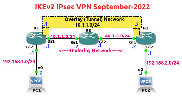
The IP addresses of the three routers and end-devices have already been configured.

I’ve highlighted the overlay and underlay interfaces, IP addresses and networks in the topology above.

IKEv2 VPN Configuration – 8 Steps

For convenience and easy understanding, I’ve divided the configuration of our Site-to-Site IKEv2 VPN into eight steps:

1. IKEv2 Proposal
2. IKEv2 Policy
3. IKEv2 Keyring
4. IKEv2 Profile
5. IPsec Transformset
6. IPsec Profile
7. Tunnel Interface
8. Routing
=========================
R1 Configuration

Step 1. IKEv2 Proposal

conf t
crypto ikev2 proposal December-Proposal
encryption aes-cbc-256
integrity sha512
group 21
exit

Step 2. IKEv2 Policy

crypto ikev2 policy November-Policy
match address local 40.1.1.1
proposal December-Proposal
exit

Step 3. IKEv2 Keyring

crypto ikev2 keyring October-KEYRING
peer R2
address 40.1.2.2
pre-shared-key local R1key
pre-shared-key remote R2key
exit
exit

Step 4. IKEv2 Profile

crypto ikev2 profile September-PROFILE
authentication local pre-share
authentication remote pre-share
keyring local October-KEYRING
match identity remote address 40.1.2.2
identity local address 40.1.1.1
exit

Step 5. IPsec Transformset

crypto ipsec transform-set BT-SET esp-aes 256 esp-sha256-hmac
exit

Step 6. IPsec Profile

crypto ipsec profile BOB-IPSEC-PROFILE
set transform-set BT-SET
set ikev2-profile September-PROFILE
exit

Step 7. Configure Tunnel Interface

int tunnel 0
ip address 10.1.1.1 255.255.255.0
tunnel source 40.1.1.1
tunnel destination 40.1.2.2
tunnel mode ipsec ipv4
tunnel protection ipsec profile BOB-IPSEC-PROFILE
no shut
exit

Step 8. Configure Routing

router eigrp 20
no auto-summary
network 192.168.1.0 0.0.0.255
network 10.1.1.0 0.0.0.255
exit
================
R2 Configuration

Step 1. IKEv2 Proposal

conf t
crypto ikev2 proposal December-Proposal
encryption aes-cbc-256
integrity sha512
group 21
exit

Step 2. IKEv2 Policy

crypto ikev2 policy November-Policy
match address local 40.1.2.2
proposal December-Proposal
exit

Step 3. IKEv2 Keyring

crypto ikev2 keyring October-KEYRING
peer R1
address 40.1.1.1
pre-shared-key local R2key
pre-shared-key remote R1key
exit
exit

Step 4. IKEv2 Profile

crypto ikev2 profile September-PROFILE
authentication local pre-share
authentication remote pre-share
keyring local October-KEYRING
match identity remote address 40.1.1.1
identity local address 40.1.2.2
exit

Step 5. IPsec Transformset

crypto ipsec transform-set BT-SET esp-aes 256 esp-sha256-hmac
exit

Step 6. IPsec Profile

crypto ipsec profile BOB-IPSEC-PROFILE
set transform-set BT-SET
set ikev2-profile September-PROFILE
exit

Step 7. Configure Tunnel Interface

int tunnel 0
ip address 10.1.1.2 255.255.255.0
tunnel source 40.1.2.2
tunnel destination 40.1.1.1
tunnel mode ipsec ipv4
tunnel protection ipsec profile BOB-IPSEC-PROFILE
no shut
exit

Step 8. Configure Routing

router eigrp 20
no auto-summary
network 192.168.2.0 0.0.0.255
network 10.1.1.0 0.0.0.255
exit
==================

Some Useful IKEv2 Verify Commands

show crypto ipsec sa
show crypto session
show run | section Crypto
show crypto engine accelerator statistic
show int tunnel 0
show crypto ikev2 proposal
show crypto ikev2 policy
debug crypto engine packet
debug crypto ikev2 packet

Verifing our Crypto Configuration on R1

R1#sh run | sec crypto
[output truncated]
crypto ikev2 proposal December-Proposal
encryption aes-cbc-256
integrity sha512
group 21
crypto ikev2 policy November-Policy
match address local 40.1.1.1
proposal December-Proposal
crypto ikev2 keyring October-KEYRING
peer R2
address 40.1.2.2
pre-shared-key local R1key
pre-shared-key remote R2key
!
crypto ikev2 profile September-PROFILE
match identity remote address 40.1.2.2 255.255.255.255
identity local address 40.1.1.1
authentication remote pre-share
authentication local pre-share
keyring local October-KEYRING
crypto ipsec transform-set BT-SET esp-aes 256 esp-sha256-hmac
mode tunnel
crypto ipsec profile BOB-IPSEC-PROFILE
set transform-set BT-SET
set ikev2-profile September-PROFILE
R1#

Verifing our Crypto Configuration on R2

R2#sh run | sec crypto
[output truncated]
crypto pki certificate chain TP-self-signed-3202180324
crypto ikev2 proposal December-Proposal
encryption aes-cbc-256
integrity sha512
group 21
crypto ikev2 policy November-Policy
match address local 40.1.2.2
proposal December-Proposal
crypto ikev2 keyring October-KEYRING
peer R1
address 40.1.1.1
pre-shared-key local R2key
pre-shared-key remote R1key
!
crypto ikev2 profile September-PROFILE
match identity remote address 40.1.1.1 255.255.255.255
identity local address 40.1.2.2
authentication remote pre-share
authentication local pre-share
keyring local October-KEYRING
crypto ipsec transform-set BT-SET esp-aes 256 esp-sha256-hmac
mode tunnel
crypto ipsec profile BOB-IPSEC-PROFILE
set transform-set BT-SET
set ikev2-profile September-PROFILE
R2#

Checking Interfaces on R1

R1#sh ip int brief
Interface IP-Address OK? Method Status Protocol
GigabitEthernet1 40.1.1.1 YES manual up up
GigabitEthernet2 192.168.1.1 YES manual up up
GigabitEthernet3 unassigned YES unset administratively down down
GigabitEthernet4 unassigned YES unset administratively down down
Tunnel0 10.1.1.1 YES manual up up

Verifying PC1 to PC2 Connectivity

Successful pings and trace routes on the two end-devices confirm that our tunnel0 is working fine.

PC1 is able to ping PC2 and vice versa.

PC1> ping 192.168.2.2

192.168.2.2 icmp_seq=1 timeout
84 bytes from 192.168.2.2 icmp_seq=2 ttl=62 time=7.263 ms
84 bytes from 192.168.2.2 icmp_seq=3 ttl=62 time=6.157 ms
84 bytes from 192.168.2.2 icmp_seq=4 ttl=62 time=5.959 ms
84 bytes from 192.168.2.2 icmp_seq=5 ttl=62 time=8.569 ms

PC1> trace 192.168.2.2
trace to 192.168.2.2, 8 hops max, press Ctrl+C to stop
1 192.168.1.1 5.999 ms 2.019 ms 1.617 ms
2 10.1.1.2 12.953 ms 3.600 ms 4.169 ms
3 *192.168.2.2 9.599 ms (ICMP type:3, code:3, Destination port unreachable)
PC1>

PC2> ping 192.168.1.1
84 bytes from 192.168.1.1 icmp_seq=1 ttl=254 time=13.269 ms
84 bytes from 192.168.1.1 icmp_seq=2 ttl=254 time=4.614 ms
84 bytes from 192.168.1.1 icmp_seq=3 ttl=254 time=5.469 ms
84 bytes from 192.168.1.1 icmp_seq=4 ttl=254 time=5.382 ms
84 bytes from 192.168.1.1 icmp_seq=5 ttl=254 time=4.964 ms

PC2> trace 192.168.1.1
trace to 192.168.1.1, 8 hops max, press Ctrl+C to stop
1 192.168.2.1 3.267 ms 7.103 ms 2.253 ms
2 *10.1.1.1 28.731 ms (ICMP type:3, code:3, Destination port unreachable) *
PC2>
===============================================

Verifying Routing on R1

The show ip route command shows that the 192.168.2.0 is being reached via the overlay network (see below).

R1#sh ip route
Codes: L – local, C – connected, S – static, R – RIP, M – mobile, B – BGP
D – EIGRP, EX – EIGRP external, O – OSPF, IA – OSPF inter area
N1 – OSPF NSSA external type 1, N2 – OSPF NSSA external type 2
E1 – OSPF external type 1, E2 – OSPF external type 2
i – IS-IS, su – IS-IS summary, L1 – IS-IS level-1, L2 – IS-IS level-2
ia – IS-IS inter area, * – candidate default, U – per-user static route
o – ODR, P – periodic downloaded static route, H – NHRP, l – LISP
a – application route
+ – replicated route, % – next hop override, p – overrides from PfR

Gateway of last resort is 40.1.1.2 to network 0.0.0.0

S* 0.0.0.0/0 [1/0] via 40.1.1.2
10.0.0.0/8 is variably subnetted, 2 subnets, 2 masks
C 10.1.1.0/24 is directly connected, Tunnel0
L 10.1.1.1/32 is directly connected, Tunnel0
40.0.0.0/8 is variably subnetted, 2 subnets, 2 masks
C 40.1.1.0/24 is directly connected, GigabitEthernet1
L 40.1.1.1/32 is directly connected, GigabitEthernet1
192.168.1.0/24 is variably subnetted, 2 subnets, 2 masks
C 192.168.1.0/24 is directly connected, GigabitEthernet2
L 192.168.1.1/32 is directly connected, GigabitEthernet2
D 192.168.2.0/24 [90/26880256] via 10.1.1.2, 00:37:51, Tunnel0

R1#sh ip route 192.168.2.2
Routing entry for 192.168.2.0/24
Known via “eigrp 20”, distance 90, metric 26880256, type internal
Redistributing via eigrp 20
Last update from 10.1.1.2 on Tunnel0, 00:38:18 ago
Routing Descriptor Blocks:
* 10.1.1.2, from 10.1.1.2, 00:38:18 ago, via Tunnel0
Route metric is 26880256, traffic share count is 1
Total delay is 50010 microseconds, minimum bandwidth is 100 Kbit
Reliability 255/255, minimum MTU 1438 bytes
Loading 1/255, Hops 1
R1#
================================

Some Crypto Verify Commands on R1

Now it’s time to get going with a bunch of crypto commands and examine the output.

R1#show crypto ikev2 sa detailed
IPv4 Crypto IKEv2 SA

Tunnel-id Local Remote fvrf/ivrf Status
1 40.1.1.1/500 40.1.2.2/500 none/none READY
Encr: AES-CBC, keysize: 256, PRF: SHA512, Hash: SHA512, DH Grp:21, Auth sign: PSK, Auth verify: PSK
Life/Active Time: 86400/3224 sec
CE id: 1001, Session-id: 1
Status Description: Negotiation done
Local spi: 0F77C00D167A34BE Remote spi: F14374F7D1885E3D
Local id: 40.1.1.1
Remote id: 40.1.2.2
Local req msg id: 0 Remote req msg id: 2
Local next msg id: 0 Remote next msg id: 2
Local req queued: 0 Remote req queued: 2
Local window: 5 Remote window: 5
DPD configured for 0 seconds, retry 0
Fragmentation not configured.
Dynamic Route Update: enabled
Extended Authentication not configured.
NAT-T is not detected
Cisco Trust Security SGT is disabled
Initiator of SA : No

IPv6 Crypto IKEv2 SA
R1#
================================
R1#show crypto ipsec sa

interface: Tunnel0
Crypto map tag: Tunnel0-head-0, local addr 40.1.1.1

protected vrf: (none)
local ident (addr/mask/prot/port): (0.0.0.0/0.0.0.0/0/0)
remote ident (addr/mask/prot/port): (0.0.0.0/0.0.0.0/0/0)
current_peer 40.1.2.2 port 500
PERMIT, flags={origin_is_acl,}
#pkts encaps: 740, #pkts encrypt: 740, #pkts digest: 740
#pkts decaps: 740, #pkts decrypt: 740, #pkts verify: 740
#pkts compressed: 0, #pkts decompressed: 0
#pkts not compressed: 0, #pkts compr. failed: 0
#pkts not decompressed: 0, #pkts decompress failed: 0
#send errors 0, #recv errors 0

local crypto endpt.: 40.1.1.1, remote crypto endpt.: 40.1.2.2
plaintext mtu 1438, path mtu 1500, ip mtu 1500, ip mtu idb GigabitEthernet1
current outbound spi: 0xA5DADA1A(2782583322)
PFS (Y/N): N, DH group: none

inbound esp sas:
spi: 0xA7E95D48(2817088840)
transform: esp-256-aes esp-sha256-hmac ,
in use settings ={Tunnel, }
conn id: 2004, flow_id: CSR:4, sibling_flags FFFFFFFF80000048, crypto map: Tunnel0-head-0
sa timing: remaining key lifetime (k/sec): (4607999/3596)
IV size: 16 bytes
replay detection support: Y
Status: ACTIVE(ACTIVE)

inbound ah sas:
inbound pcp sas:
outbound esp sas:
spi: 0xA5DADA1A(2782583322)
transform: esp-256-aes esp-sha256-hmac ,
in use settings ={Tunnel, }
conn id: 2003, flow_id: CSR:3, sibling_flags FFFFFFFF80000048, crypto map: Tunnel0-head-0
sa timing: remaining key lifetime (k/sec): (4607999/3596)
IV size: 16 bytes
replay detection support: Y
Status: ACTIVE(ACTIVE)
outbound ah sas:
outbound pcp sas:
================================
R1#show crypto session
Crypto session current status

Interface: Tunnel0
Profile: September-PROFILE
Session status: UP-ACTIVE
Peer: 40.1.2.2 port 500
Session ID: 2
IKEv2 SA: local 40.1.1.1/500 remote 40.1.2.2/500 Active
IPSEC FLOW: permit ip 0.0.0.0/0.0.0.0 0.0.0.0/0.0.0.0
Active SAs: 2, origin: crypto map
================================

Some Crypto Verify Commands on R2

R2#show crypto ikev2 sa detailed
IPv4 Crypto IKEv2 SA

Tunnel-id Local Remote fvrf/ivrf Status
1 40.1.2.2/500 40.1.1.1/500 none/none READY
Encr: AES-CBC, keysize: 256, PRF: SHA512, Hash: SHA512, DH Grp:21, Auth sign: PSK, Auth verify: PSK
Life/Active Time: 86400/246 sec
CE id: 1001, Session-id: 1
Status Description: Negotiation done
Local spi: F14374F7D1885E3D Remote spi: 0F77C00D167A34BE
Local id: 40.1.2.2
Remote id: 40.1.1.1
Local req msg id: 2 Remote req msg id: 0
Local next msg id: 2 Remote next msg id: 0
Local req queued: 2 Remote req queued: 0
Local window: 5 Remote window: 5
DPD configured for 0 seconds, retry 0
Fragmentation not configured.
Dynamic Route Update: enabled
Extended Authentication not configured.
NAT-T is not detected
Cisco Trust Security SGT is disabled
Initiator of SA : Yes

IPv6 Crypto IKEv2 SA
================================
R2#show crypto ipsec sa

interface: Tunnel0
Crypto map tag: Tunnel0-head-0, local addr 40.1.2.2

protected vrf: (none)
local ident (addr/mask/prot/port): (0.0.0.0/0.0.0.0/0/0)
remote ident (addr/mask/prot/port): (0.0.0.0/0.0.0.0/0/0)
current_peer 40.1.1.1 port 500
PERMIT, flags={origin_is_acl,}
#pkts encaps: 86, #pkts encrypt: 86, #pkts digest: 86
#pkts decaps: 87, #pkts decrypt: 87, #pkts verify: 87
#pkts compressed: 0, #pkts decompressed: 0
#pkts not compressed: 0, #pkts compr. failed: 0
#pkts not decompressed: 0, #pkts decompress failed: 0
#send errors 0, #recv errors 0

local crypto endpt.: 40.1.2.2, remote crypto endpt.: 40.1.1.1
plaintext mtu 1438, path mtu 1500, ip mtu 1500, ip mtu idb GigabitEthernet1
current outbound spi: 0x533E0924(1396574500)
PFS (Y/N): N, DH group: noneDecember-Proposal

inbound esp sas:
spi: 0x30612CC1(811674817)
transform: esp-256-aes esp-sha256-hmac ,
in use settings ={Tunnel, }
conn id: 2002, flow_id: CSR:2, sibling_flags FFFFFFFF80000048, crypto map: Tunnel0-head-0
sa timing: remaining key lifetime (k/sec): (4607990/3244)
IV size: 16 bytes
replay detection support: Y
Status: ACTIVE(ACTIVE)

inbound ah sas:
inbound pcp sas:
outbound esp sas:
spi: 0x533E0924(1396574500)
transform: esp-256-aes esp-sha256-hmac ,
in use settings ={Tunnel, }
conn id: 2001, flow_id: CSR:1, sibling_flags FFFFFFFF80000048, crypto map: Tunnel0-head-0
sa timing: remaining key lifetime (k/sec): (4607994/3244)
IV size: 16 bytes
replay detection support: Y
Status: ACTIVE(ACTIVE)

outbound ah sas:
outbound pcp sas:
================================
R2#show crypto session
Crypto session current status

Interface: Tunnel0
Profile: September-PROFILE
Session status: UP-ACTIVE
Peer: 40.1.1.1 port 500
Session ID: 1
IKEv2 SA: local 40.1.2.2/500 remote 40.1.1.1/500 Active
IPSEC FLOW: permit ip 0.0.0.0/0.0.0.0 0.0.0.0/0.0.0.0
Active SAs: 2, origin: crypto map

Overall, it seems like our IKEv2 Site-to-Site VPN configuration is working fine.

IPv4 & IPv6 – 13 Differences

 Networking  Comments Off on IPv4 & IPv6 – 13 Differences
Sep 162022
 

Before jumping into the differences between IPv4 and IPv6 addresses, let’s first consider what an IP (Internet Protocol) address is.

An IP address (either IPv4 or IPv6) uniquely identifies a host or device on a network, and can be a source or destination address.

Your computer, mobile phone, router, Roku box, Layer 3 switch, Firewall, Xbox, surveillance camera, baby monitor, etc., all have IP addresses.

When you access a web site on the Internet or other resources on the corporate Intranet, you’re actually visiting an IP address lurking behind a domain name like apple.com or cisco.com.

One Caveat for Network Newbies: Subnet addresses, multicast addresses, broadcast addresses and Link Local addresses look like IP addresses but they cannot be applied to hosts/end devices/servers/router interfaces, etc. The explanation for that is beyond the scope of this post.

With that brief intro to an IP address, let’s take a look at the differences between an IPv4 address and an IPv6 address:

Difference 1: Available or Exhausted?

IPv4 addresses are almost exhausted today.

Network Address Translation, Private IP Addresses and Classless Inter-Domain Routing (CIDR) pushed the day of reckoning for IPv4 but that day seems to have arrived now.

Today, when you sign up for a web hosting account or a new mobile phone service, you’re more than likely to be alloted an IPv6 address.

There’s plentiful supply of IPv6 addresses. Almost as many as grains of sand on this planet, according to some network gurus.

IPv4 represents the past and a fading present while IPv6 represents growth and the future.

But for the forseeable future, IPv4 and IPv6 addresses will continue to co-exist.

Difference 2: Number of Bits in IP Address

An IPv4 address is 32-bits long, divided into four octets of 8-bits each.

On the other hand, IPv6 address is 128-bit long and divided into eight hextets of 16-bits each.

Difference 3: Number of Possible Addresses

IPv4 offers about 4.3 Billion Addresses.

While you may be tempted to think 4.3 billion IPv4 addresses is a lot, it really is not.

Some Class A addresses (10.0.0.0/8) are not publicly routable on the Internet as are some parts of Class B and Class C.

Despite efforts like CIDR (Classless Inter-Domain Routing), Private IPv4 addresses and NAT (Network Address Translation), we have almost run out of IPv4 addresses.

Widespread use of the Internet in all geographies, explosion in cell phone and other mobile devices and growth of IoT (Internet of Things) devices like surveillance cameras, connected exercise machines, etc., have accelerated depleion of IPv4 addresses and spurred the transition to IPv6 addresses.

What about total number of IPv6 addresses?

Hold on to your seat tight now because the answer is stupifying: 340 Undecillion.

So what in the heck does 340 Undecillion mean?

340,282,366,920,938,000,000,000,000,000,000,000,000
or
2^128
or
3.402823669×10³⁸

Difference 4: Dotted Decimal vs Hexadecimal

The next key difference between an IPv4 and IPv6 address is in the way the address is represented.

An IPv4 address is usually represented in dotted decimal format.

Here are some examples of IPv4 addresses in Dotted Decimal format:

8.8.8.8 (Google’s DNS server IPv4 address)
10.2.3.1 (a private IPv4 address).
130.23.5.2
200.176.200.91

But an IPv6 address is represented in hexadecimal format.

An IPv6 address consists of 32 hexadecimal digits, with each hex digit representing 4-bits.

Each set of 4 hex digits is separated by a colon.

Example of a publicly routable IPv6 address in Hexadecimal format:
2001:5421:007A:0000:0000:842C:CAFE:4299

Difference 5: Numbers or Alphabets

An IPv4 address includes only numbers.

However, an IPv6 address can include both numbers and alphabets (but only from A-F).

Difference 6: Abbrevation & Expansion

Not surprisingly, an IPv6 address can be summarized or expanded depending on the address.

Leading 0s in an address can be manipulated but not trailing 0s. Also, two or more continuous hextets of 0s can be written as :: but done so only once.

Example 1: Leading 0s can be Supressed:
2001:5421:000A:0000:0000:842C:CAFE:4299
can be written as
2001:5421:A:0000:0000:842C:CAFE:4299
or even
2001:5421:A::842C:CAFE:4299

Example 2: Trailing 0s MUST Not be Touched
2001:6200:000A:0000:0000:842C:CAFE:4299
The two 0s after 62 in the second hextet cannot be removed.

But an IPv4 address does not lend itself to abbreviation or expansion.

Difference 7: Size of Header

IPv4 header size is 20-bytes long while the header size in IPv6 is 40-bytes.

Although the header size is larger in IPv6, it is considered to be simpler compared to the IPv4 header.

Difference 8: What about Classes?

IPv4 addresses are broadly divided into five Classes (A-E).

For instance, Class D addresses are Multicast addresses.

Although the importance of Classes has diminished because of innovations like Classless Inter-Domain Routing (CIDR), classes are still an inalienable element of IPv4.

There are no classes in IPv6 addresses.

Difference 9: Different Routing Tables

There are separate routing tables for IPv4 and IPv6 addresses.

An IPv4 packet is routed to its destination via the IPv4 routing table.

Similarly, an IPv6 packet is routed by referencing the IPv6 routing table.

For instance, when you issue the show ip route command, you’ll see only the IPv4 routing table.

To see the IPv6 routing table, you’ll have to issue the command: show ipv6 route.

During migration from IPv4 to IPv6, organizations go in for “dual stack” or the concept of a router being able to route both IPv4 and IPv6 packets.

Difference 10: Issue of Fragmentation

Fragmentation of packets is permitted in IPv4.

Fragmentation refers to breaking up packets into smaller chunks when they exceed the Maximum Transmission Unit.

But fragmentation is not permitted with IPv6.

When packets exceed the MTU at IPv6 supporting routers they will be dropped.

Difference 11: ARP vs NDP

Address Resolution Protocol (ARP), which maps IPv4 Addresses to MAC addresses, is supported only in IPv4.

IPv6 addresses rely on Neighbor Discovery Protocol (NDP).

Difference 12: More Configuration Options

IPv6 offers more configuration options compared to IPv4.

With IPv4, it’s either manual (static) configuration or relying on Dynamic Host Configuration Protocol (DHCP). There are exceptions like Automatic Private (APIPA) for Windows systems.

When it comes to IPv6, there are two static configuration methods (manual and eui-64) and two dynamic configuration (dhcp and autoconfig) methods.

Difference 13: Loopback Address is Different

While troubleshooting network issues, Network engineers or students preparing for CCNA or CCNP exams use the Loopback address to test if the network protocol stack is working fine.

Unsurprisingly, the loopback address we use for testing is different in IPv4 and IPv6.

In IPv4, the loopback address is usually 127.0.0.1 while it’s ::1 in IPv6.

IPv6 Ping
jack@mypc:~$ $ ping ::1
PING ::1(::1) 56 data bytes
64 bytes from ::1: icmp_seq=1 ttl=64 time=0.042 ms
64 bytes from ::1: icmp_seq=2 ttl=64 time=0.040 ms
64 bytes from ::1: icmp_seq=3 ttl=64 time=0.048 ms
64 bytes from ::1: icmp_seq=4 ttl=64 time=0.057 ms
64 bytes from ::1: icmp_seq=5 ttl=64 time=0.068 ms
^C
— ::1 ping statistics —
5 packets transmitted, 5 received, 0% packet loss, time 4079ms
rtt min/avg/max/mdev = 0.040/0.051/0.068/0.010 ms

IPv4 Ping
jack@mypc:~$ ping 127.0.0.1
PING 127.0.0.1 (127.0.0.1) 56(84) bytes of data.
64 bytes from 127.0.0.1: icmp_seq=1 ttl=64 time=0.032 ms
64 bytes from 127.0.0.1: icmp_seq=2 ttl=64 time=0.038 ms
64 bytes from 127.0.0.1: icmp_seq=3 ttl=64 time=0.042 ms
64 bytes from 127.0.0.1: icmp_seq=4 ttl=64 time=0.053 ms
64 bytes from 127.0.0.1: icmp_seq=5 ttl=64 time=0.061 ms
64 bytes from 127.0.0.1: icmp_seq=6 ttl=64 time=0.074 ms
64 bytes from 127.0.0.1: icmp_seq=7 ttl=64 time=0.074 ms
^C
— 127.0.0.1 ping statistics —
7 packets transmitted, 7 received, 0% packet loss, time 6128ms
rtt min/avg/max/mdev = 0.032/0.053/0.074/0.015 ms